Manufacturing types
Composite brushes and hard metal deburring
CeramiX® nylon abrasive brushes are designed for use in power tools, robotic cells and CNC applications to eliminate the need for time-consuming and inconsistent hand deburring operations.
SIT’s exclusive access to Ceramix®’ product catalog expands the industrial brush offering available to our customers with a strong focus on special abrasive filaments like ceramic and diamond abrasive nylon.
Materiali
These abrasive nylon brushes are made with CeramiX® filament molded into a urethane based composite hub construction.
CeramiX® provides enhanced cutting action up to 3 to 5 times faster than traditional abrasive filaments. The mineral wears away in smaller pieces, consistently leaving more mineral in the filament to work on the part surface.
There are indeed three key traits which contribute to this filament elevated status:
- fracture toughness
- hardness
- self-sharpening qualities
These features equate to increased productivity for CeramiX® abrasive nylon brush filaments, made with proprietary 3M™ 321 ceramic abrasive grain (available in 220, 180, 120, 80 and 46 grit size) embedded through the filament.


Test 1: Aluminium Plate 1750 RPM

Test 2: CRS Plate 1750 RPM
Grit size and filament diameter
| Grana | Diametro filamento / Filament diameter | ||
|---|---|---|---|
| Grit | mm | inch | |
| 46 | 1,65 x 2 | 0,065" x 0,080" | * sezione ovale / oval shape |
| 1,7 x 2,3 | 0,068" x 0,090" | ||
| 80 | 1 | 0,040" | |
| 1.4 | 0,055" | ||
| 1,1 x 2,3 | 0,045" x 0,090" | * sezione rettangolare / rectangualr shape | |
| 120 | 0.7 | 0,028" | |
| 1 | 0,040" | ||
| 180 | 0.9 | 0,035" | |
| 220 | 0.6 | 0,22" | |
I filtri standard forniti per macchinari CNC (carta, tessuto,viscosa, feltro) sono studiati per filtrare particelle fino a 5 micron – 0.0002″. Rivolgersi al fornitore per la scelta del filtro più opportuno.
Conversion chart Grit size - Microns - Inches
| Grana / Grit Size | Micron (valore medio / average) | Inch (valore medio / average) |
|---|---|---|
| 46 | 356 | 0.014 |
| 60 | 254 | 0.010 |
| 80 | 165 | 0.0065 |
| 100 | 122 | 0.0048 |
| 120 | 102 | 0.0040 |
| 180 | 76 | 0.0030 |
| 220 | 63 | 0.0025 |
| 240 | 50 | 0.0020 |
| 320 | 31 | 0.00122 |
| 500 | 19 | 0.00075 |
| 800 | 12 | 0.00047 |
| 1000 | 7 | 0.00028 |
Each abrasive grain has a different dimension. In table the avarage value is provided.
Types of composite brushes
Operating Parameters
Starting RPM and Motor size
| D | Dry RPM | Motor | |
|---|---|---|---|
| mm | inch | ||
| 50 | 2 | 1750 - 2500 | 1/4 HP |
| 76 | 3 | 1750 - 2500 | 1/4 HP |
| 102 | 4 | 1750 - 2500 | 1/4 HP |
| 127 | 5 | 1500 - 1750 | 1/4 HP |
| 152 | 6 | 1250 - 1750 | 1/2 HP |
| 203 | 8 | 800 - 1200 | 3/4 HP |
| 254 | 10 | 700 - 800 | 1 HP |
| 305 | 12 | 600 - 700 | 1 HP |
| 355 | 14 | 500 - 600 | 1 HP |
Initial speeds and motor size for Wheel Brushes
| D | Dry RPM | Motor | |
|---|---|---|---|
| mm | inch | ||
| 50 | 2 | 1750 - 2500 | 1/4 HP |
| 76 | 3 | 1750 - 2500 | 1/4 HP |
| 102 | 4 | 1750 - 2500 | 1/4 HP |
| 127 | 5 | 1500 - 1750 | 1/4 HP |
| 152 | 6 | 1250 - 1750 | 1/2 HP |
| 203 | 8 | 800 - 1200 | 3/4 HP |
| 254 | 10 | 700 - 800 | 1 HP |
| 305 | 12 | 600 - 700 | 1 HP |
| 355 | 14 | 500 - 600 | 1 HP |
LENGEND
D = Disk or wheel diameter
Dry RPM = Racommended starting RPM for dry applications
Motor = Recommended motor size horse power (based on a 25mm – 1″ brush face)
* RPM for wet application (use of coolants) can be up to 40% more than the dry RPM value, compatibly with the brush and the tool’s MAX RPM rated value.
Feed rate on different materials
| Velocità Avanzamento / Feed Rate | ||
|---|---|---|
| mm/min | inch/min | |
| Acciaio Inox - Leghe d'acciaio / Stainless Steel - Alloy Steel | 300→450 | 12→18 |
| Acciaio dolce - Ghisa / Mild Steel - Cast Iron | 630→760 | 25→30 |
| Alluminio - Non ferrosi / Aluminium - Non ferrous | 890→1270 | 35→50 |
Abrasive nylon disc brushes work best at speeds allowing fairly deep penetration of the workpiece into the brush filaments. Faster speeds do not typically work as well as slower speeds, since the maximum RPM listed on the brush is not the optimum working speed. A good rule of thumb is to stay below 13 m/s – 2,500 ft/min in dry applications and 18 m/s – 3,500 ft/min with coolant.
Coolant is always recommended for applications requiring high speeds, high penetration or on very thin parts.

ROTATIONAL DIRECTION
On the initial pass of the brush, rotation should be in the opposite direction of the cutting tool that created the burr (same rotation, opposite direction).
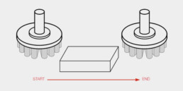
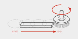
BRUSH PATH
The ideal brush path is in the opposite direction of travel from the cutting tool that created the burr. The brush path should also be longer than the cutting tool path, to a point where the trailing edge of the brush is effective on the end of the part.
The brush should start and finish its path and rotation completely off the workpiece.
Lastly, to maximize the amount of filament that is striking the part, the centerline of the brush should be offset from the center of the part (most important if the piece is bigger than the brush).
Once the first path is finished it’s recommended to change rotational direction and set a new path opposite to the first one in order to remove any burr left.

FILAMENT WEAR COMPENSATION
As referred in the “How to choose the right brush” section, on CNC machinery it’s possible to monitor the load on drive motors and adjust the position of the brushing tool in order to keep a fixed interference or pressure for the best working performance and for a lower filament wear. There are 4 most common ways to compensate the brush tool wear on these machines:
Automatic indexing: Program an adjustment (indexing the tool on the Z axis) after a predetermined number of produced parts
Probing: Numerical Control centers sometimes have the capability to probe the face of the brush in order to adjust the right interference of the filament tips with the workpiece
Amperage metering: A fixed pressure can be controlled by monitoring the amp reading of the drive motor
Manual indexing: where other methods can’t be used the operator can adjust manually the interference based on visual inspection or on statistical process control of the processed parts


Deburring on CNC machine advantages
- Improved process:
- No hand deburring and other operations outside the automatic processing phase
- Simplified production cycle (time and cost)
- Less time and cost for logistics and product handling
- Improved quality:
- Extreme precision in deburring every piece
- Homogeneous deburring on each piece
- Standardization and repeatability of the process